Comparing any two CAD models can be a difficult task, especially when making sure a translated or revised 3D CAD model maintains integrity for geometry, dimensions, and other data.
With nearly 30 years in field of CAD data translation & validation, Capvidia has written this guide on understanding all things CAD validation.
What is CAD validation?
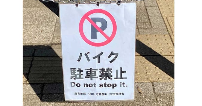
Language translation isn't always done right. CAD translation isn't always done right, either.
CAD validation is the process of verifying that a translated or revised CAD file matches the authority/native model.
Validation checks for geometry, 3D annotations (GD&T), volume, surface area, center of mass, etc. to answer one question: has the design intent of the authority remain unchanged?
The authority CAD model is typically a native CAD file: CATIA, Creo, Inventor, NX, SolidWorks, etc.
The translated CAD file is often a CAD-neutral file called a derivative: IGES, STEP, QIF, etc.
CAD validation can also include revision checks (e.g. Creo 6 Rev 1 to Creo 6 Rev 2) or version checks (e.g. Creo 6 to Creo 7).
What CAD validation checks for:
- Detect translation errors.
- Geometry / design defects or changes.
- PMI (product manufacturing information) changes.
- Quality defects or changes.
- Revisions: Intended or unintended.
- Part or assembly structure.
Why is CAD validation important?
CAD validation is part of the growing practice of model-based definition with design and manufacturing workflows transitioning from paper-based (engineer drawings) to model-based (CAD model).
When a CAD model is translated from an native to a derivative or when a revision is made, CAD validation ensures both models are identical. This allows the derivative to be safely used downstream in the product lifecycle through manufacturing, quality, supply chain, and more.
Design problems left unchecked and unsolved eventually become bigger and more costly errors downstream leading to scrapped parts, rework, delays, and the dreaded recall.
|
Product lifecycle phase
|
Cost of corrective action
|
|
Requirements
|
1 (reference case)
|
|
Design
|
3 to 8 times
|
|
Build
|
7 to 16 times
|
|
Test
|
21 to 78 times
|
|
Operations
|
29 to 1,615 times – mean of 250 times (recall)
|
This is a classic case of GIGO (garbage in, garbage out). No matter how skilled the engineer and how powerful the tools, using a bad derivative leads to bad results downstream.
Cost and time savings are much greater when errors are caught in the design stage compared to later in the product lifecycle, so it’s best to catch errors early.
Who requires CAD validation?
CAD validation is typically done on the manufacturing side or whoever carried out the CAD translation. Usually, suppliers to large OEMs are in charge of CAD model validation.
For example, Boeing suppliers and sub-tier suppliers are required to validate that their own 3D CAD models match authority CAD models. So partners and suppliers using different CAD/CAE/CAM/CMM software must validate.
Job titles that handles validation duties include IT, manufacturing engineer, quality engineer, mechanical engineer, design engineer, and project engineer.
Industries that heavily rely on CAD validation include defense and aerospace, automotive, heavy equipment, consumer electronics, and healthcare.
What are the best CAD formats/ derivatives for validation?
Although CAD neutral files like IGES, STL, ACIS, and 3D PDF are popular files for geometry, Capvidia recommends 3D CAD files with semantic PMI (GD&T, 3D annotations, BoM, notes, etc.) that are model-based definition (MBD) ready.
The two best MBD CAD files are QIF and STEP AP242.
Both are ISO standards and are the start of digital manufacturing/ Industry 4.0 initiatives.
When to do CAD validation:
- Any CAD translation: CAD to CAD, legacy to current system, etc.
- Manufacturing interoperability from CAD to CAM, CMM, CNC, etc.
- Revision to revision comparison: Are all changes intended?
How is CAD validation done?
Engineers use CAD validation software to verify their derivatives or revision changes.
CAD validation software like CompareVidia must be robust and typically have these features:
ONE: It’s powerful and accurate.
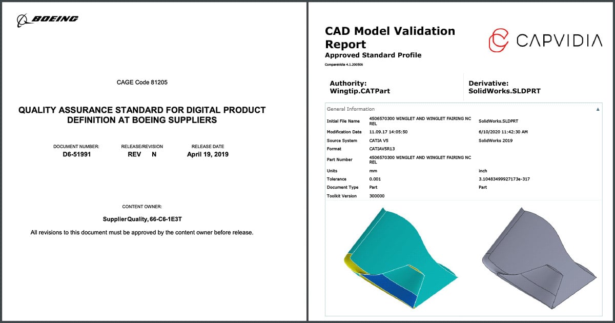
The best way to tell is if the CAD validation software is trusted to meet or exceed Boeing’s D6-51991 DPD requirements, which is very strict and rigorous.
[Editor’s note: CompareVidia is one of the few Boeing DPD-approved software].
TWO: It produces a detailed PASS/FAIL report.
The report should inspect CAD geometry, PMI, assembly structure, and more--highlighting all changes and deviations from the authority.
THREE: It’s compatible with many CAD formats.
At a minimum, it should be able to validate native CAD files (CATIA, Creo, Inventor, NX, and SolidWorks) and CAD-neutral files (IGES, STL, STEP, and QIF).
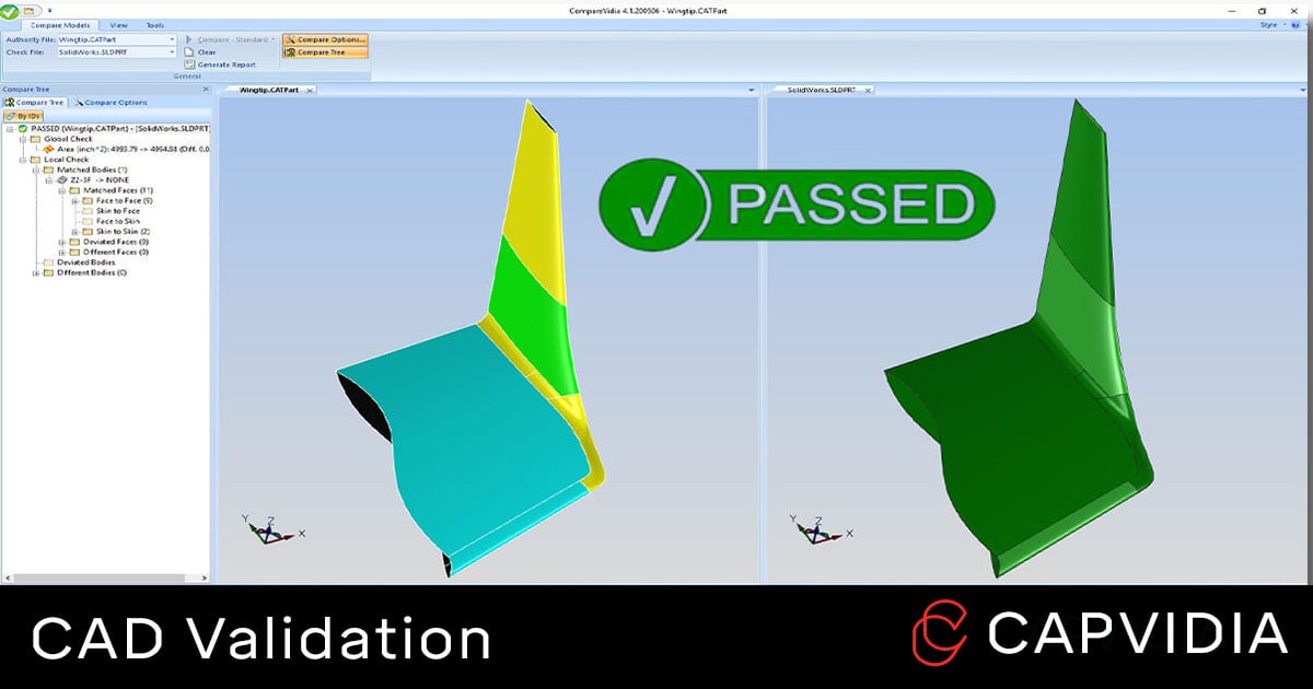
A typical CAD validation workflow looks like this:
- Authority and derivative model are loaded on software.
- Both are compared & validated.
- Detailed Report is generated for pass/fail.
Example of CompareVidia, CAD validation software, in action.
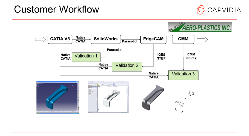
In this use case, one of our customers, Aero-Plastics, validate their model three times.
First validation: They receive a native CATIAV5 model from their customer. Aero-Plastics translates the CATIAV5 into SolidWorks--their 3D CAD design software.
Second validation: The SolidWorks model is translated into Edgecam for CNC.
Third validation: After the part is manufactured, they compare points exported from their CMM.
CAD validation and interoperability between different systems equals happy customer.

Easy & powerful derivative CAD validation & revision comparison.
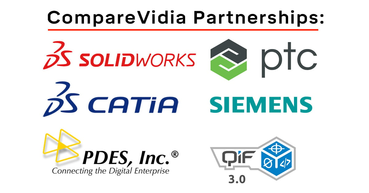
Trusted by our partners: SolidWorks, NX, CATIA, PTC, STEP AP242 (PDES), QIF (DMSC), and Spatial.

What happens if my CAD validation fails?
Besides good CAD validation software, another important factor is having a GOOD translated model.
Sub-par derivatives and translations will create issues, and no CAD validation software will able to PASS a poorly translated model.
It all begins with creating a solid derivative CAD file.
Based on 16 years of doing CAD validation for major OEMs and suppliers, we've collected the major reasons why CAD validation fails:
- Model Tolerances: Each CAD system has their own tolerance to control the accuracy of their models. This can lead to interoperability issues, especially for complex data.
- Poor CAD quality: Most CAD data is not designed with translation in mind. Design practices done in one CAD system may be passable, but can cause issues when translated into another
- Extra data: CAD Systems enable to you export all kinds of data, and some of this data you don’t need to validate.
- Multiple translations: Sometimes a CAD model can get translated several times using several different translators. The accuracy of a CAD model will never improve when it gets translated. It can only get worse.
- Formats: There are many different CAD formats and flavors of them. Translating from one format to the next inherently causes issues.
- Different Coordinate Systems: Some validation tools can't properly realign models in different coordinate systems..
A good translated CAD model and a good CAD validation software will only get you so far.
When it comes to troubleshooting and facing an issue you can't solve, having a reliable partner is also crucial when it comes to support.
It's not about software, it's 100% about solutions. So having a partner provide real customer support and not only a download file is key when it comes to successful CAD validation.
FAQ
Q: Is there a way to avoid CAD validation?
A: Yes, have all companies, departments, teams, team members, partners, suppliers, and others who handle CAD data use the same native CAD system. Good luck with that.
As CAD technology grows and becomes more utilized downstream--with different software, formats, and department needs, CAD validation becomes even more important.
Q: What are the repercussions of not validating CAD?
A: Scrap, rework, recall, bloated cost and loss of time--errors caught in the design phase saves up to 2x in cost compared to errors caught in manufacturing, up to 10x caught in testing, and up to 200X caught in operations.
Q: What about CAD translation?
A: CAD translation is the first half of the journey. It's important to have good derivative file for validation to compare.
Need to learn more about CAD validation?

Capvidia is a leader in CAD translation & validation, especially pertaining to digital transformation and the MBD journey. Have questions? Talk to our team today.