CAD
Top 8 Neutral 3D CAD File Formats
Learn more about the best neutral CAD file formats for translation from your native CAD software.
With over dozens of CAD software and an equal amount of CAD file types, we look at the best translation-friendly CAD formats for importing and exporting.
With over dozens of CAD software and even more CAD file formats, importing & exporting the right format helps tremendously when it comes to data integrity and minimizing errors & rework.
This is especially true for downstream applications from design to manufacturing.
With nearly 30 years of CAD data translation, Capvidia is here to provide better understanding about 3D CAD translation and converting to the best formats.
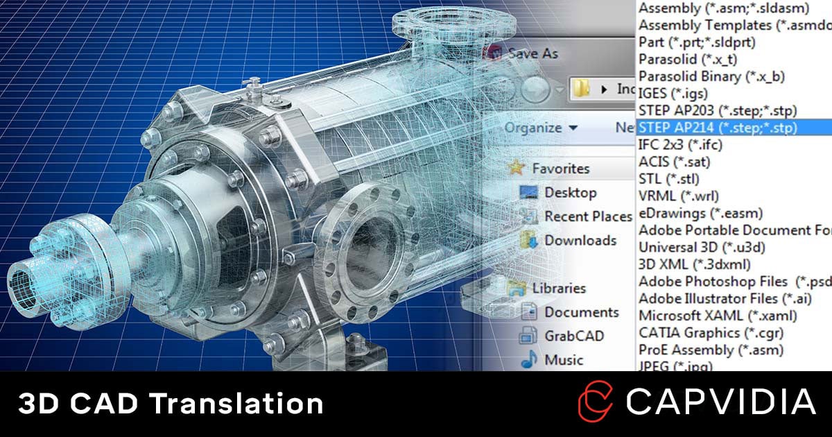
3D CAD translation is the process of exporting or converting a native CAD file format (CATIA, Creo, SolidWorks, Inventor, etc.) to a neutral CAD file format (IGES, STEP, QIF, etc. ).
The objective is to have two models are identical in their geometry, 3D annotations, volume, surface area, etc.
The goal is have a compatible CAD file format for downstream use in other CAD, CAE, CAM, and CMM programs.
| Major CAD Software | Developer | Major Import/ Export CAD Files |
| CATIA | Dassault Systemes | 3D XML, CATIA V5, CATIA V4, CATIA V3,DXF , IGES, STEP, and VRML |
| NX | Siemens | ACIS, CATIA V5, CATIA V4, DXF/DWG, IGES, STEP, STL |
| Creo | PTC | ACIS, DXF/DWG, IGES, JT, NX (import only), Parasolid, PDF, SolidEdge (import only), SolidWorks (import only), and STEP. |
| SolidWorks | Dassault Systemes | ACIS, CATIA V5, DXF/DWG, IGES, Parasolid, PDF (export only), STEP, and STL. |
| Inventor | Autodesk |
ACIS, CATIA V5, DWG, IGES, JT, Parasolid, STEP. |

It's important to note that we're recommending CAD files that are standards.
Standards have a known structure, are documented, and governed by an international or national standards body like the International Standards Organization (ISO), American Society of Mechanical Engineers (ASME) or American National Standards Institute (ANSI) to name a few.
They provide a common, well-defined language that two software systems can use to communicate with each other.
As digital transformation sweeps across manufacturers, suppliers, and factories, MBD (model-based definition) CAD is slowly but surely becoming a future practice of MCAD as the next generation of engineers work directly in the 3D model to include GD&T, BOM, 3D annotations, notes and other data instead of a 2D drawing-based workflow.
MBD-ready neutral CAD files include product manufacturing information (information usually conveyed in a 2D drawing) that allows for a single source of truth from design to manufacturing--being both human-readable and machine-readable.
With that in mind, Capvidia strongly recommends translation-friendly formats that are standards and MBD-ready such as STEP AP242, QIF, and JT.
STEP (Standard for the Exchange of Product model data) files are ubiquitous across multiple CAD software and used across multiple industries.
It is interoperable between different systems including CAD, CAM, CAE, CAI, CMM, etc.
In regards to mechanical CAD, there are three major STEP file formats:
Both STEP AP203 and STEP AP214 have been replaced by STEP AP242 and is a great starting point for sharing a neutral CAD file.

QIF (Quality Information Framework) format is a newer CAD format that is made for 21st technology such as automation, Big Data, and IoT.
Although its excels with semantic PMI, which allows for human & machine-readable CAD, interoperability, and MBD workflows, data can also be looped back for future insights and inventions which potentially produces the most value for any company.
QIF is highly valued in Metrology and Quality departments, and gaining strong support in the model-based enterprise community.
JT (Jupiter Tessellation) files known for visual representation, but it can also have full B-rep and PMI, making it MBD-ready for Siemens users.
It's internal B-rep representation is flexible, including support for STEP and Parasolid. If a JT exported from NX contains B-rep data, it will be in the Parasolid format.
Although JT is technically an open format, many vendors utilize Siemen's JT Open Toolkit. This toolkit is particularly important if dealing with Parasolid data, which makes use of blends with proprietary recipes. Because of this, it isn't quite widely accepted as STEP or QIF and less common outside Siemens software environments.

Capvidia leads the field in MBD CAD translation & validation. We'll be happy to help (depending on amount of good coffee or tea that day).
Neutral CAD files are intermediary files used to translate data between CAD systems. They work extremely well for visual representation or wireframe geometry. IGES and STL are also standards which ensures smooth import/export between CAD systems.
IGES (Initial Graphics Exchange Specification) files are the first, and therefore, oldest neutral CAD file. Although technically superseded by STEP and QIF, it’s been around so long that it has widespread adoption from many CAD software.
It supports surface geometry and solids, although it’ll be more prone to errors such as gaps between surfaces, missing faces, wrong orientation, and lost of history depending on the export options.
STL files are mesh models and are about surface geometry and shapes. However, it doesn’t include colors, textures, and other model attributes.
So what is it good for?
Rapid prototyping, some CAM software, and especially 3D printing where it’s a common file.
ACIS and PARASOLID are the two most used kernels.
ACIS is maintained by Dassault Systemes and used in many CAD, CAM, CAE, and CMM software.
Companies and products using the ACIS kernel: AutoDesk, BricsCAD, Cimatron, Colbat, IronCAD, Mitutoyo, SpaceClaim, ZEISS CALYPSO, and others.
Parasolid is maintained by Siemens and used in many CAD, CAM, and CAE software.
Companies and products using the Parasolid kernel: Abaqus FEA, ADINA, ANSYS, MasterCAM, NX, Onshape, SimScale, SolidWorks, SolidEdge, T-Flex, and others.
Capvidia is proponent of MBD data, so we’d recommend exporting into STEP and QIF as a best practice, especially if your department or company is exploring digital transformation or model-based enterprise.
However, if the stars align, and your downstream departments or partners also use the same CAD system or same kernel as your design team, then these are the recommended ways to share the data:
Q: Is it possible to convert from one proprietary CAD file to another (e.g. Creo to SOLIDWORKS)?
A: No, proprietary CAD formats cannot translate nor convert to another. The best method is to translate a neutral CAD like STEP, QIF, or IGES.
Q: How do I know if I have a properly translated CAD file?
A: CAD validation ensures both the authority and derivative are matching.
Q: How does model quality affect data translation?
A: A poor quality authority model will lead to a poor quality converted CAD file. This is based on model tolerances and design practices for a specific CAD vs another, extra data, and other factors.
Q: What's the best tool for translating or converting to CAD formats? (shameless plug)
A: MBDVidia is a 3D CAD MBD workflow and translation software used by major OEMs for downstream use. Specific use cases: FAI, CMM, and automated visual inspection.
Q: What makes CAD translation for MBD neutral CAD vs non-MBD neutral CAD different?
A: While non-MBD neutral CAD translates for geometry, MBD neutral CAD translates the geometry and the PMI (product manufacturing information) which contains all the information to build and measure the part aka the heart of the MBD process.
Capvidia is a leader in CAD translation & validation, especially pertaining to digital transformation and the MBD journey. Have questions? Talk to our team today.
Learn more about the best neutral CAD file formats for translation from your native CAD software.
STEP AP203 vs AP214 vs AP242: What are the key differences? We also look at which CAD systems import and export STEP files.
QIF, or the Quality Information Framework, is the XML framework that has become the standard for computer-aided quality measurement systems...