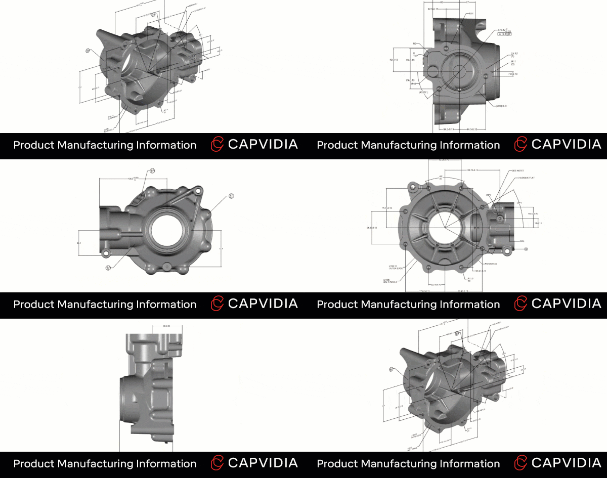
Product manufacturing information (PMI) is design, manufacturing, quality, and other data included in a 3D CAD file.
Anything conveyed in a 2D drawing to build and measure a part can be upgraded to 3D annotations to help automate tasks, create downstream interoperability, and maintain various data from a single source of truth.
PMI is governed by ASME and ISO industry standards.
PMI includes the following information:
- GD&T (Geometric dimensions & tolerances).
- Bill of materials (BOM).
- Surface finish.
- Weld symbols.
- Material specifications.
- Metadata & notes.
- History of engineering change orders.
- Legal/proprietary/export control notices.
- Other definitive digital data.
Why is PMI important
MBD (model-based definition) is the practice of using a 3D CAD model + semantic PMI (machine-readable PMI) to drive downstream efficiency: automated tasks, reduced scrap and rework, improved product iteration and timelines, and interoperability among all stakeholders in a product lifecycle.
It’s part of the digital transformation in manufacturing known as Industry 4.0 that highlights the use of IoT (Internet of Things), smart technology, and Big Data.
PMI plays a significant role because it enables a transition from 2D drawing-based workflows to a 3D model-based workflow which provides the next generation of manufacturing processes.
Benefits of using PMI

Process & Automation
With traditional 2D drawing-based workflows, many tasks are done manually, taking up quality time from skilled engineers from doing higher-level work.
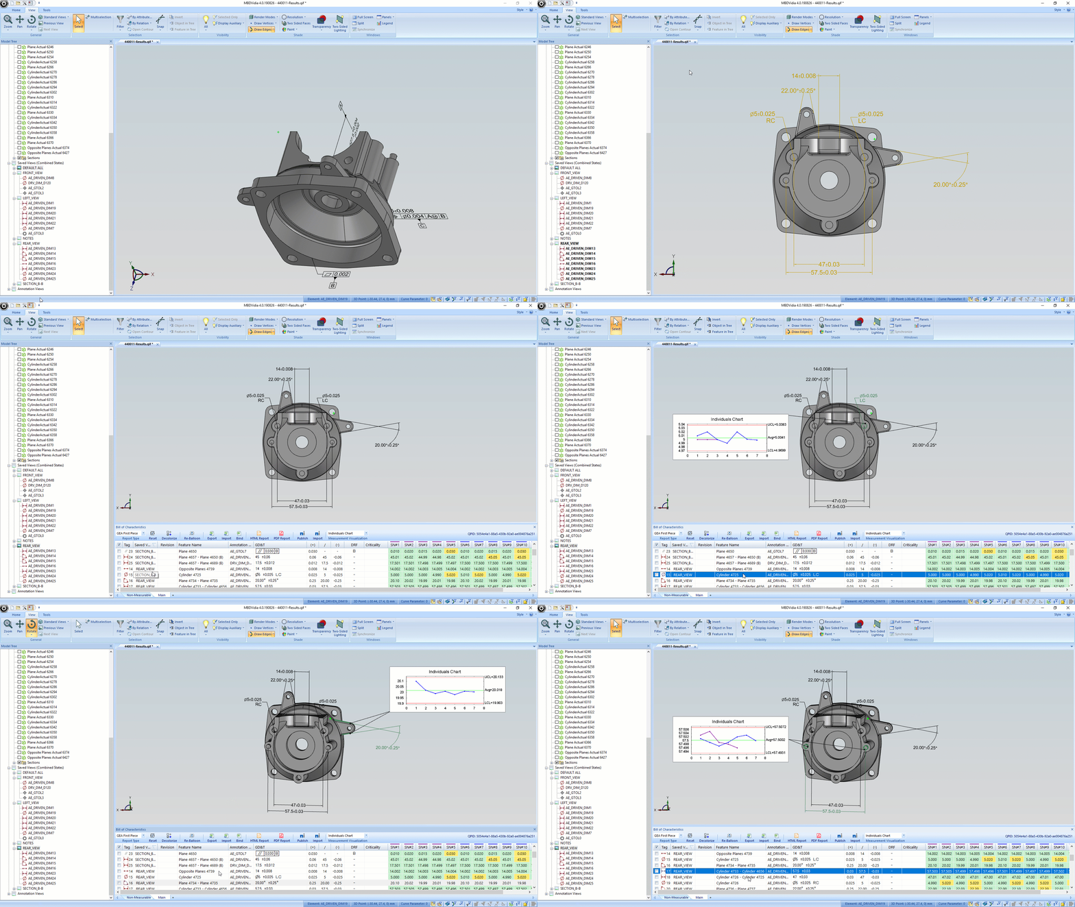
Manufacturing and quality control engineers manually enter & sometimes interpret GD&T and other details into their CMM (coordinate-measuring machine), CAM (computer aided manufacturing), or CAI (computer aided inspection) software. Depending on the complexity of the part, it can take days if not weeks.
Same can be said for other tasks such as generating a first article inspection report. PMI would include the necessary GD&T, BOM, or data to automatically be consumed by machines and software, therefore saving time and reducing any human error such as interpretation or transcription.
Prevention & Root Cause
Because MBD and its PMI data is derived from a single source of truth and are machine-readable, unvalidated engineering changes and unintended deviations are caught earlier in the lifecycle thus reducing scrapped parts, missed deadlines, and most importantly, the dreaded recall.
Semantic PMI can be read by different CAD/CAM systems.
Data & Analytics
The wild, wild west of enterprise manufacturing is collecting and harvesting data for improving products and businesses.
Most data during quality and inspection validates pass/fail decisions but is rarely reintroduced to the product lifecycle for evolutionary or revolutionary insights.
In a digital world where data is the new oil, there’s plenty of opportunity and impactful future use cases as IoT, AI, and Big Data become part of the manufacturing ecosystem.
Financial Impact
Public studies with MBD and PMI have shown a reduction of 80% of hours in annotating, machine, and inspection and up to 81% reduction in CMM workflow.
Private studies involving Capvidia customers have seen process time & cost savings (FAI/PPAP, CMM, CAD translation & validation, engineering change orders, etc.) ranging from 50% to 90%.
Manufacturing companies that embrace digital transformation in general see improved quality up to 35% while reducing cost up to 20-30%.
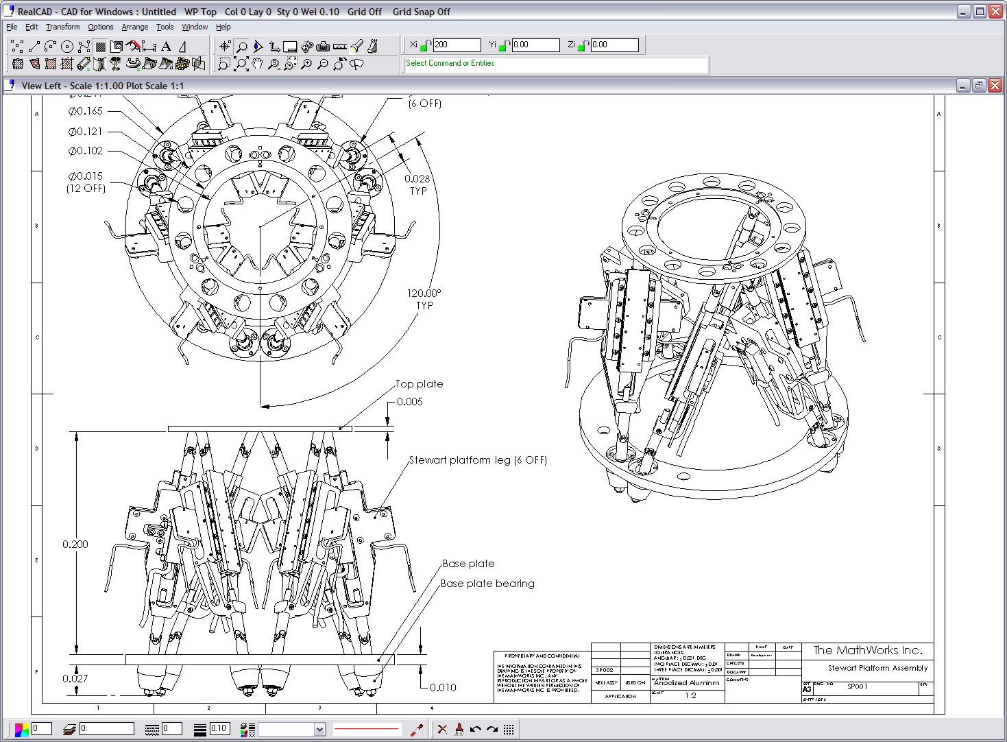
Top 10 Pitfalls of 2D Drawings
- Not machine-readable.
- 3D visualization is mainstream, mobile, and affordable.
- Wasted effort to recreate 2D from 3D.
- Less information available — the product will exist in 3 dimensions, why reduce its definition to 2?
- More prone to interpretation and data inaccuracies. Up to 60% of 2D drawings do not match 3D models.
- Aren’t adequate to convey design intent.
- More back and forth and time wasted on clarifying designs.
- Not suitable for cross-department collaboration.
- Another document to the pile & workflow.
- Simple change in production definition requires changes to all 2D documentation.
Need to learn more about applying PMI to your CAD?
From software to service solutions, Capvidia has helped companies with MBD initiatives with definitive time and cost savings.
Challenges to adopting PMI

More Upfront Work
Design engineers switching from a 2D drawing to 3D model-based workflow would initially see additional effort ranging from 1.3 to 1.5X during the learning process. Even though the downstream benefits would provide more ROI and process efficiency for the company, design engineers wouldn’t be able to see immediate benefits for themselves.
New Skillsets Needed
2D drawings are more flexible with interpretation. With semantic PMI, no corners are cut, since it has to be machine-readable.
Therefore, engineers must have the necessary skills to create and interpret GD&T according to best practices such as ASME Y14.5 and ASME Y14.41.
Cultural Shift
Traditional practices and processes are about repeatability & stability. In the world of manufacturing, this is the gold standard.
However, the dynamic changes in today’s business climate, time-to-market with innovation, and cost-cutting are three important factors when companies must face when staying relevant.
There’s a tipping point when a company is just producing a faster horse while the competition innovates with a car.
21 Reasons Why PMI (Product Manufacturing Information) is Important
People:
- Man hours saved: up to 80% time saved compared to drawing-centric approach.
- Frees up engineering time for improving design and products.
- Communicates designer’s intent.
- Next generation of engineers see and design in 3D.
- Improves engineer skillset to learn and apply new insights.
Process:
- Single source of truth & data authority.
- Reduces human error through typing or interpretation.
- Eliminates redundant annotations.
- Up-to-up information embedded & easily revisable.
- Machine-readable 3D CAD & PMI for automation.
- Removes the middleman or engineering drawings.
- More feature-rich data for better instructions for the end-user.
- More iteration and process breakthrough improvement.
- Higher quality inspections with measurement optimization algorithms.
- Reusable information housed in a single source across multiple lifecycles & processes.
- Better two-way communication and easier collaboration among stakeholders.
Product:
- Part of MBD process: Better products, better pricing, better margins.
- Shorter product development cycles, faster time to market.
- Global interoperable standard at the software level.
- Enables MBE (model-based enterprise): Staying competitive, first-mover advantage.
- Scalable practice from one part to one department to one factory to enterprise-wide.
How to implement PMI

Capvidia recommends pilot projects such as automating manual tasks such as FAI, ballooning, CMM, etc. before moving onto bigger model-based enterprise initiatives. Start small and grow from there:
- Define people who are directly involved with 2D drawings.
- Document current practices, communication exchange, and technologies.
- Identify a pilot project.
- Get design or drafting team to start implementing PMI onto 3D model.
- Work with downstream departments and team to use 3D model + PMI.
- Track progress.
- Measure ROI.
- Take insights and expand into next MBD project while building up MBD education.
Need Help Integrating PMI to Your 3D CAD or MBD process?
Contact us today and our solutions team can answer every question you have from multi-CAD compatibility to First Article Inspection.


