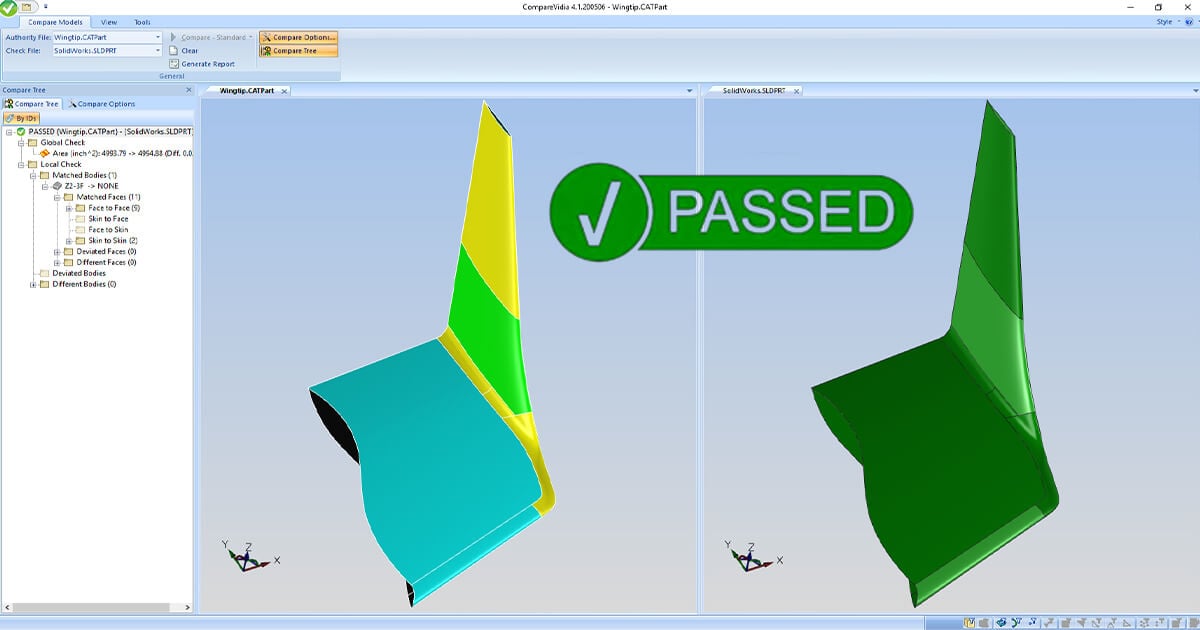
Load any 3D CAD model and check the derivative against the authority model. B-rep, point-cloud, and mesh–all acceptable.
Compatible with Creo, SolidWorks, NX, CATIA, Inventor, QIF, STEP AP242, IGES, STL and more.
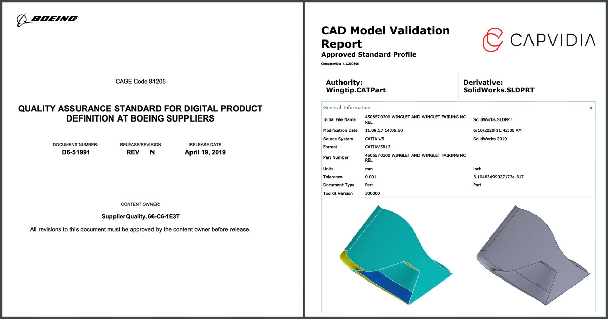
Adheres to Boeing D6-51991 Quality Assurance Standard for Digital Product Definition at Boeing Suppliers and other aerospace standards for Airbus, Lockheed Martin, United Launch Alliance, Northrup Grumman, and more. In a few easy steps, you get a validation report that you can present to your auditor.
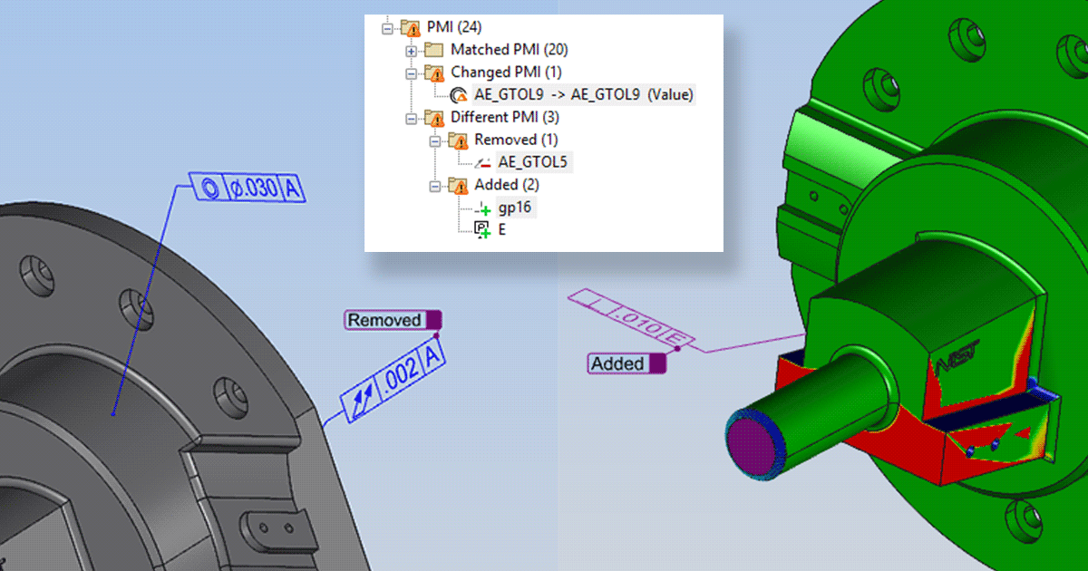
Compare GD&T, notes, and 3D annotations that are machine-readable for MBD use.
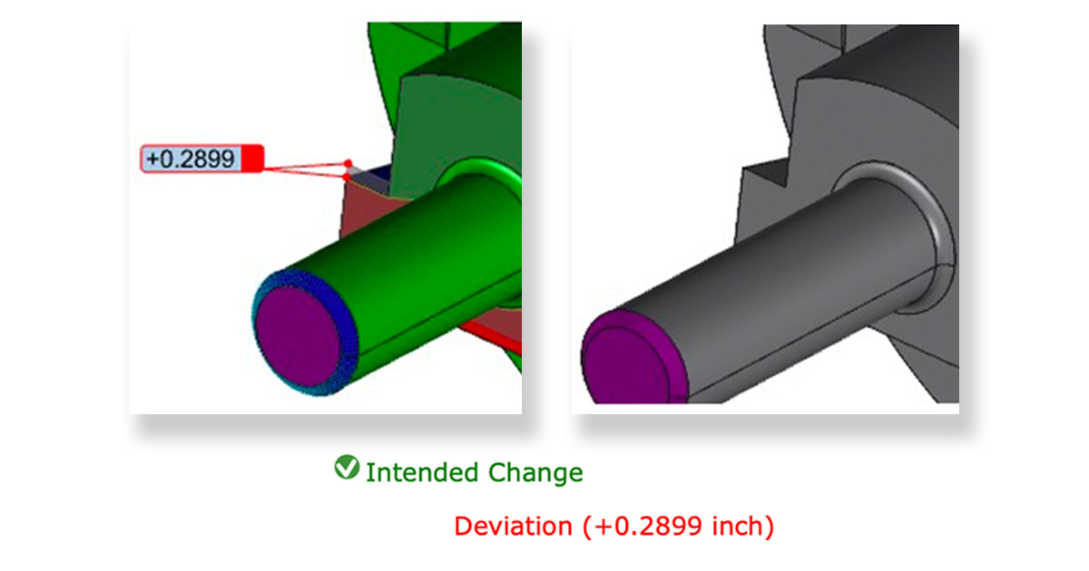
Compare two revisions of a CAD model. Mark any changes as “Intended” or “Unintended.”
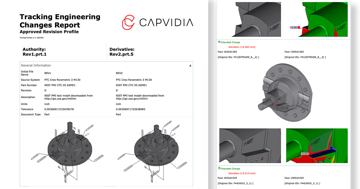
Digitally certified pass/fail reports inspecting CAD geometry, PMI, assembly structure and more.
Our software is second to none when it comes to CAD validation & revision comparison. Request a trial evaluation for CompareVidia to start your digital transformation journey.